- 您现在的位置:买卖IC网 > Sheet目录1991 > CS5340-CZZ (Cirrus Logic Inc)IC ADC AUD 101DB 200KHZ 16-TSSOP
AN249
3
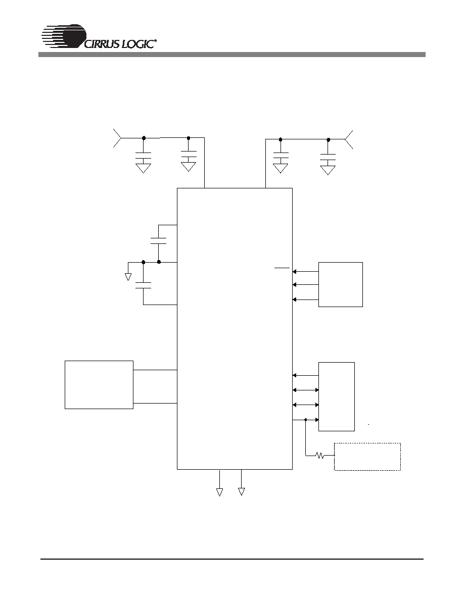
3. Typical Connection Diagrams
Figures 1 and 2 illustrate the typical connection diagram for the CS5333 and CS5340 respectively. The
analog and digital core of the CS5333 are powered from VA, which can be set from 1.8 V to 3.3 V. The
VL supply pin powers the digital interface logic from 1.8 V to 3.3 V and can be set independently from VA.
Figure 1. CS5333 Typical Connection Diagram
VA
CS5333
AINL
AINR
GND
TST
Analog Input Filter
Figure 3
FILT+
REF_GND
VQ
1.8 V to 3.3 V
+
1.8 V to 3.3 V
1 F
1 F
1
F
0.1 F
VL
0.1 F
+
1 F
RST
DIF
DIV
Mode
Configuration
MCLK
LRCK
SCLK
Digital
Audio
Source
SDATA
47k Connect to:
VL for Master Mode
GND for Slave Mode
1
2
3
4
5
6
7
8
9
10
11
12
13
16
14
15
发布紧急采购,3分钟左右您将得到回复。
相关PDF资料
CS5340-DZZR
IC ADC AUD 101DB 200KHZ 16-TSSOP
CS5341-DZZ
IC ADC AUD 105DB 200KHZ 16-TSSOP
CS5342-CZZ
IC ADC AUD 105DB 200KHZ 16-TSSOP
CS5345-CQZ
IC ADC AUD 104DB 200KHZ 48-LQFP
CS5345-DQZ
IC ADC AUD 104DB 200KHZ 48-LQFP
CS5346-CQZR
IC ADC AUD 103DB 200KHZ 48-LQFP
CS5351-BZZ
IC ADC AUD 108DB 204KHZ 24-TSSOP
CS5361-DZZ
IC ADC AUD 114DB 204KHZ 24-TSSOP
相关代理商/技术参数
CS5340-CZZ/F
制造商:Cirrus Logic 功能描述:
CS5340-CZZR
功能描述:音频模/数转换器 IC IC 101dB 192kHz Multi-bit Audio ADC RoHS:否 制造商:Wolfson Microelectronics 转换速率: 分辨率: ADC 输入端数量: 工作电源电压: 最大工作温度: 最小工作温度: 安装风格: 封装 / 箱体: 封装:
CS5340-DZZ
功能描述:音频模/数转换器 IC 101dB 192kHz Multi-Bit Audio ADC RoHS:否 制造商:Wolfson Microelectronics 转换速率: 分辨率: ADC 输入端数量: 工作电源电压: 最大工作温度: 最小工作温度: 安装风格: 封装 / 箱体: 封装:
CS5340-DZZR
功能描述:音频模/数转换器 IC IC 101dB 192kHz Multi-bit Audio ADC RoHS:否 制造商:Wolfson Microelectronics 转换速率: 分辨率: ADC 输入端数量: 工作电源电压: 最大工作温度: 最小工作温度: 安装风格: 封装 / 箱体: 封装:
CS5341
制造商:CIRRUS 制造商全称:Cirrus Logic 功能描述:105 dB, 192 kHz, Multi-Bit Audio A/D Converter
CS5341_06
制造商:CIRRUS 制造商全称:Cirrus Logic 功能描述:105 dB, 192 kHz, Multi-Bit Audio A/D Converter
CS5341_08
制造商:CIRRUS 制造商全称:Cirrus Logic 功能描述:105 dB, 192 kHz, Multi-Bit Audio A/D Converter
CS5341-CZZ
功能描述:音频模/数转换器 IC 105dB 192 kHz Multi-Bit Audio ADC RoHS:否 制造商:Wolfson Microelectronics 转换速率: 分辨率: ADC 输入端数量: 工作电源电压: 最大工作温度: 最小工作温度: 安装风格: 封装 / 箱体: 封装: